MTAC-MFSER Connector Pinout and LEDs
The MTAC-MFSER connector is one of the following:
- DTE build: 9-pin, male-D Sub through-hole connector
- DCE build: 9-pin, female-D Sub through-hole connector
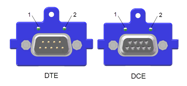
The MTAC-MFSER card contains two LEDs that are mounted on the card bracket and visible on the back panel of the Conduit housing when the card is installed. The LEDs show activity on the Rx and Tx lines.
- DTE build: LED 1 shows Rx activity and LED 2 shows Tx activity.
- DCE build: LED 1 shows Tx activity and LED 2 shows Rx activity.
The 9-pin accessory card connector includes the following:
| Pin Number | RS232 DTE Signal | RS232 DCE Signal | RS485 DTE Half Duplex | RS485 DCE Half Duplex | RS485 DTE Full Duplex | RS485 DCE Full Duplex | RS422 mode DTE | RS422 mode DCE |
|---|---|---|---|---|---|---|---|---|
| 1 | DCD (In) | DCD (Out) | RX-/TX- (In/Out)1 | N/C | TX- (Out)1 | RX- (In)1 | TX- (Out)1 | RX- (In)1 |
| 2 | RX (In) | RX (Out) | RX+/TX+ (In/Out)1 | N/C | TX+ (Out)1 | RX+ (In)1 | TX+ (Out)1 | RX+ (In)1 |
| 3 | TX (Out) | TX (In) | N/C | RX+/TX+ (In/Out)1 | RX+ (In)1 | TX+ (Out)1 | RX+ (In)1 | TX+ (Out)1 |
| 4 | DTR (Out) | DTR (In) | N/C | RX-/TX- (In/Out)1 | RX- (In)1 | TX- (Out)1 | RX- (In)1 | TX- (Out)1 |
| 5 | Ground | Ground | Ground | Ground | Ground | Ground | Ground | Ground |
| 6 | DSR (In) | DSR (Out) | N/C | N/C | N/C | N/C | RTS- (Out)2 | RTS- (In)2 |
| 7 | RTS (Out) | RTS (In) | N/C | N/C | N/C | N/C | RTS+ (Out)2 | RTS+ (In)2 |
| 8 | CTS (In) | CTS (Out) | N/C | N/C | N/C | N/C | CTS+ (In)2 | CTS+ (Out)2 |
| 9 | RI (In) | RI (Out) | N/C | N/C | N/C | N/C | CTS- (In)2 | CTS- (Out)2 |
1 Connection convention for differential pairs is DTE TX to DCE RX and DTE RX to DCE TX.
2 Hardware handshake is not part of the standard RS422 interface but is available in this interface.