MTAC-GPIO Connector and Cable Pinout
The 14-pin accessory card connector includes the following:
- 4 digital inputs
- 3 analog inputs
- 4 digital outputs
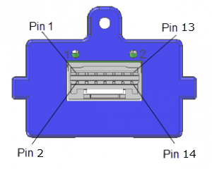
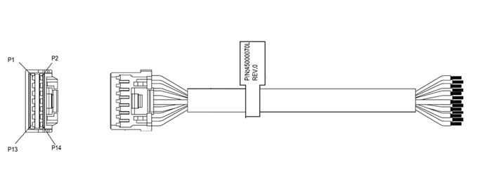
| Pin Number | Name | Wire Color | Description |
|---|---|---|---|
| 1 | External Input 1 | black | General-Purpose Input. Can handle up to 30 VDC. |
| 2 | External Input 2 | white | General-Purpose Input. Can handle up to 30 VDC. |
| 3 | External Input 3 | red | General-Purpose Input. Can handle up to 30 VDC. |
| 4 | External Input 4 | yellow | General-Purpose Input. Can handle up to 30 VDC. |
| 5 | External Input Common Ground | purple | General-Purpose Input. Isolated from system ground. |
| 6 | Analog Input 1 | blue | Analog input range 0-5 VDC. |
| 7 | Analog Input 2 | brown | Analog input range 0-5 VDC. |
| 8 | Analog Input 3 | green | Analog input range 0-5 VDC. |
| 9 | Analog Input Ground | grey | Common ground to the 3 analog inputs. General-Purpose Input. Not isolated from system ground. |
| 10 | External Output 1 | light blue | Open Collector output – 55 VDC max 300 mA max current. |
| 11 | External Output 2 | orange | Open Collector output – 55 VDC max 300 mA max current. |
| 12 | External Output 3 | light green | Open Collector output – 55 VDC max 300 mA max current. |
| 13 | External Output 4 | pink | Open Collector output – 55 VDC max 300 mA max current. |
| 14 | External Output Ground | white/black | Common ground to the 4 external outputs. Not isolated from system ground. |