Search Results

Keyword: ‘packet forwarder’

Conduit AP

March 24th, 2017 Comments off

MTCAP

Conduit® AP (MTCAP and MTCAP2 ) connects thousands of IoT assets to the cloud using the LoRaWAN® protocol. It expands LoRa network coverage to difficult to reach areas and is capable of packet forwarding user data between LoRa end points and a centrally located network server on the cloud, in a data center, or a public network.

Documentation

Software

Note: Some mLinux and LoRa topics do not apply to the MTCAP, which is a gateway/packet-forwarder only.

Related


Categories: Tags:

GPSD

January 27th, 2017 Comments off

This feature is only available on certain products and models (not available with all devices).

NOTE: Prior to mLinux/AEP 5.0.0 gpsd usage of the GPS was not compatible with lora-packet-forwarder. It was not possible to use the Multitech supplied Lora-Packet-Forwarder with the GNSS port, and GPSD at the same time. This was fixed in the 5.0.0 releases.

GPSD Overview

GPSD is the server that monitors the GNSS/GPS (if included with your device) and makes time and position information available to client programs, such as gpsmon and NTPD.  GPSD communicates with NTPD via shared memory to provide the GPS time.  The server allows multiple programs to use the GNSS/GPS.  It also detects leap second and tells NTPD of an upcoming leap second and its direction on the day of the leap second.

The script /usr/sbin/gpsd_fixed has no parameters, but uses the file /etc/default/gpsd which contains the parameter, GPSFIX, as a criteria to determine if the GNSS/GPS currently has a fix (lock) on the satellites. If there is a fix, it creates a file /var/run/gpsfix, with the contents equal to the actual GPS fix value found. Otherwise the file is deleted. The script /usr/sbin/gpsd_settime checks for a GPS fix. If so, it sets the system clock to the GPS time, first using the GNSS/GPS, in case there is a huge change, then using ntpd -gq to get it much closer.

NTP/NTPD ultimately manages the time based reliability and availability of time sources (with top priority going to the GPS time). For more information on NTPD and how it manages time, see the NTPD page.

Here are the key files for setup of the GPSD on the device:

  • GPSD configuration file is located in /etc/default/gpsd. This file is set up for u-Blox, the proprietary communications protocol for the u-Blox chip used on the device.
  • GPSD init script is located in /etc/init.d/gpsd. This file can be used to start GPSD manually.
  • mtsio configuration file is located in /etc/default/mts-io. This determines whether or not the GNSS/GPS is reset during boot. After a reset, the GPS takes some time to acquire the satellite information.
  • gpsfix file is created after the GPS has a fix on the satellites indicating that the GPS now has valid data.

GPSD configuration file

Here is the default configuration file, /etc/default/gpsd:

ENABLED="yes"
GPSD_SOCKET="/var/run/gpsd.sock"
GPSD_OPTIONS="-n -D 1"

# Conduit 0.1 GPS devices
GPS_LINE=/dev/ttyXRUSB2

# Highest speed permitted by uBlox.
GPS_BAUD=115200
GPS_DEVICES="$GPS_LINE /dev/pps0"

GPS_FIXFILE=/var/run/gpsfix

# GPSD/UBlox Lock requirement
# Create GPS_FIXFILE when reached.# UBlox NAV SOL (0x01 0x06) at gpsFix value
# and above
# 00 No Fix
# 01 Dead reckoning only
# 02 2D fix
# 03 3D fix
# 04 GPS + dead reckoning combined
# 05 Time only fix
GPSFIX="03 05"

The GPSD program uses the uBlox proprietary binary message mode to communicate with the GPS as the most efficient method.

Here are the major elements of the GPSD configuration file:.

  • GPSD_SOCKET can be used to communicate with GPSD.
  • GPSD_OPTIONS for the program include:
    • -D specifies the debug level. We use 1 in the example file above.
    • -n causes the GPSD daemon to immediately start communicating with the GPS.
    • GPS_LINE indicates the Serial driver name for the GPS.
    • GPS_BAUD shows baud rate set to 115200. At a baud rate of 9600, the device does not get the GPS messages quickly enough.
    • GPS_FIXFILE contains GPSFIX level as contents. This file indicates the GPS is ready to use.
    • GPSFIX assigns the valid FIX values that should be found in the NAV SOL message from the GPS. The values indicate the GPS is ready to use.

gpsmon utility

The GNSS/GPS output may be observed using the gpsmon utility. gpsmon works best using ssh and ethernet with the device.

To run the utility, enter the following command:

mtcdt: gpsmon

The resulting output displays:

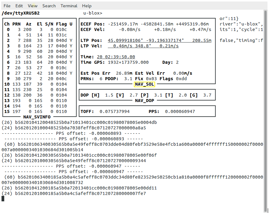
Notice the box with the label NAV_SOL at the bottom. In this box, the bottom line is Fix 0x03. This is one of the acceptable values mentioned in /etc/default/gpsd for GPSFIX.

With the value of GPSFIX set to 03 05 in the configuration file, either 0x03 or 0x05 is acceptable in the gpsmon output.

Bash script to check GNSS/GPS status

This bash script is located in  /usr/sbin/gpsd_fixed on the device. It uses the utility, gpsmon, to determine when the GPS fix field in the UBX NAV SOL message indicates a fix matching one of the fixes of the GPSFIX variables specified in the configuration file (/etc/default/gpsd). The fix choices in the GPSFIX variable are space separated and the values are in hex, but no value over 05 is allowed.

Here is how the bash script works:

1. To execute the bash script, enter the command:

mtcdt: /usr/sbin/gpsd_fixed

2. The script returns an exit status of 0 if one of the fixes specified is achieved.

3. One of the following occurs next:

a. If the script executes and one of the GPSFIX values is achieved, the GPS fix field value is placed in the file GPS_FIXFILE, as specified in /etc/default/gpsd.

OR

b. If the fix value is not one of the values specified in GPSFIX, the file GPS_FIXFILE is removed. The GPS is not ready yet. Wait and try again.

4. From powerup, it takes six to ten minutes before the GPS fix reaches 0x03, which is a 3D fix.

Bash script to set the system clock

This bash script sets the system clock using gpsmon output if /usr/sbin/gpsd_fixed indicates the GPS fix.

To execute this script, enter the following:

mtcdt:/usr/sbin/gpsd_settime

This is needed prior to starting NTPD to prevent the GPS from being marked as a falseticker.

Using gpsd with the gpsd python library

The gpsd python library is contained in the following package:

python-pygps

This library is provided on the mLinux image, and from the Downloads page, the item named Pre-built Packages.

Using the library in a python script will require the following import statement:

from gps import *

You can download an example here:

testgps.txt

Note: You need to rename  the file as testgps.py.

Output of testgps.py:

$ testgps.py
fix          3
longitude    -93.196113443
latitude     45.099362019
time utc     2017-11-28T20:41:00.000Z
altitude     285.846
epv          8.74
ept          0.005
speed        0.101
climb        -0.025

Satellites (total of 14  in view)
PRN:   1  E:  18  Az: 319  Ss:  37  Used: y
PRN:  10  E:  67  Az: 117  Ss:  23  Used: n
PRN:  11  E:  19  Az: 303  Ss:  36  Used: y
PRN:  12  E:  18  Az:  79  Ss:  16  Used: n
PRN:  14  E:  59  Az: 268  Ss:  45  Used: y
PRN:  18  E:  35  Az: 125  Ss:  17  Used: n
PRN:  22  E:   5  Az: 303  Ss:  26  Used: n
PRN:  24  E:  20  Az:  46  Ss:  21  Used: y
PRN:  25  E:  15  Az: 117  Ss:  21  Used: n
PRN:  31  E:  25  Az: 197  Ss:  38  Used: y
PRN:  32  E:  76  Az: 305  Ss:  41  Used: y
PRN: 131  E:  33  Az: 212  Ss:  40  Used: n
PRN: 135  E:  25  Az: 230  Ss:  37  Used: y
PRN: 138  E:  36  Az: 200  Ss:  36  Used: y


There is a gpsd library for C++, C, Java, and perl.  For more information see:

http://catb.org/gpsd/client-howto.html

Categories: Tags:

Creating a Custom Application

July 8th, 2016 Comments off

NOTE: Support for Node-RED/Node.js on Multitech AT91SAM9G25-based products was discontinued within mPower 5.3.  For mPower 5.3.3 to 5.3.8, users can install Node-RED as a custom application. mPower 6.0 or later no longer supports this custom app option. For alternative code examples in Python, see Example Applications below.

Any instructions related to Node-RED/Node.js are still applicable for mPower MTCDT 5.2.1 and MTCAP 5.2.1 and earlier on all devices. And also applies to any non-AT91SAM9G25-based products.

The AEP firmware version 1.3 or later supports installing and running user-created custom applications as well as managing them from DeviceHQ®. You can disable Node-RED to save system resources.

Basic Requirements:

  • Use a supported language: C/C++, Python, Nodejs* (Note: mPower 5.3.8 or lower supports Python 2.7.)
  • For details on the latest supported version of Yocto, refer to Introduction to Yocto.
  • The app can be installed either on an SD card or in flash.
    • You can use an optional boolean variable to manage this or otherwise the app-manager takes care of it automatically based on the presence of an SD card. See manifest.json Details for more information.
  • Application is packaged as a gzipped tar file containing all required files.
  • Use the new app-manager program on the Conduit to manage custom apps
    • This is exclusively used to install, uninstall, start, and stop custom apps.

*Note Nodejs is not supported for Multitech AT91SAM9G25-based products with mPower 5.3 or higher.

Required Application Structure

tarball

All required files must be present for successful installation.

How to Create a Custom Application

  1. Download the custom app SDK template and extract the enclosed template tarball into your application directory.
  2. Modify manifest.json to contain the information about your app. See manifest.json Details for more information.
  3. Set up app dependencies:
    1. If your app doesn’t have dependencies to install, remove the two sample IPK entries in provisioning/p_manifest.json
    2. If your app does have dependencies to install:
      1. Create IPK files of all dependencies and place them in the provisioning directory
      2. Update provisioning/p_manifest.json with all your IPK dependency files.
    3. See p_manifest.json Details for more information
  4. Modify the Install script if you need extra dependency installation or other install setup beyond installing IPK files. This script is used to install and uninstall your app. See Install Script for more details.
  5. Modify the Start script to start and stop your application process(es) as needed. See Start Script for more details.
  6. If you have config files you want to update through DeviceHQ, place them in the config directory.
  7. Modify status.json with the default AppInfo string of your choosing. See status.json Details for more details.
  8. Organize the rest of your application content within this directory any way you like. The Conduit only cares about the location of the required and optional files noted above.
  9. Create a gzipped tar file (tarball) of this directory, ensuring all required files are present and correct. The tarball doesn’t need to match the app name in manifest.json. The first level application content like manifest.json must be at the top level of the tarball just like the custom app template. To create a tarball on Linux:
    $ cd <your_top_level_app_directory>
    $ tar --hard-dereference -hczf <path_to_create_tgz>.tgz *

Example Applications (including Python alternatives to Node-RED)


Use Monit to Monitor Custom Apps

You can also use monit to monitor your custom applications. Refer to the monit page for information on installation of the monit package and its use.

Backup Custom Apps with User-Defined Defaults (UDD)

You can backup/save Custom Apps when you save them in User Defined Defaults of the device. You must install them in the /var/config  directory using the User Defined Defaults feature.

Categories: Tags:

Conduit mLinux: Advanced LoRa Configuration

September 3rd, 2015 Comments off
This topic applies only to mLinux installations.

Additional LoRa configuration fields in /var/config/lora/lora-network-server.conf:

Item Description
db Non-volatile location of the LoRa network server database file.
backupInterval Interval in seconds to backup database to non-volatile memory.
lora LoRa network configuration:
Item Description
frequencyBand 868 or 915.
channelPlan Set of frequencies and datarates to use for uplink and downlink channels. EU868, US915, AU915, AS923, IN865, RU864 or KR920.
frequencySubBand Sub-band for US operation, 1-8.
rx1DatarateOffset Datarate offset for mote RX window 1 sent in join response (0-3).
rx2Datarate Datarate for mote RX window 2 sent in join response (7-12).
maxTxPower Max TX power (dBm), -6 to 26.
antennaGain Gain of external antenna in dBi, default: 3
deviceQueueSize Max number of downstream messages in queue per each device.
frequencyEU Center frequency for extra EU channels (Hz). (865.5-867.5 or 869.4 MHz)
frequencyAS Center frequency for extra AS channels (Hz). (920.5-922.6 or 924.1-927.5 MHz)
frequencyKR Center frequency for extra KR channels (Hz). (921.3-921.5 or 922.9 MHz)
netID Net ID for beacon packets and assigned network addresses.
beaconInterval 0:disabled, N:seconds between beacon packets, must be factor of seconds in a day.
beaconPower dBm to transmit beacon packets.
beaconFreqHop Enable/disable frequency hopping for beacons in AU or US.
beaconFrequency Frequency for beacon packets, set to 0 for default according to Channel Plan.
beaconInfoDesc gw desc indicator.
beaconLatitude Latitude value to add to beacon packets gw desc field.
beaconLongitude Longitude value to add to beacon packets gw desc field.
ADRStep Step in cB between SNR based datarate assignment for ADR
dutyCyclePeriod Length of duty-cycle sliding window in minutes. (default: 60)
minDatarate Min datarate for ADR, default: US915/AU915 DR0 – SF10BW125, EU868 DR0 – SF12BW125
maxDatarate Max datarate for ADR, default: US915/AU915 DR4 – SF8BW500, EU868 DR6 – SF7BW250
joinDelay Rx1 delay in seconds between end of tx and opening of first rx window for join accept message
rx1Delay Rx1 delay in seconds between end of tx and opening of first rx window
syncWord Sync word override to configure Sx1301 concentrator in decimal notation, (public: 52 (0x34), private: 18 (0x12))
maxEIRP AS923 max device TX power, default: 20
dwelltimeUp max dwelltime for uplink packets, default: 0 – no limit, 1 – 400 ms
dwelltimeDown max dwelltime for downlink packets default: 0 – no limit, 1 – 400 ms
enableStrictCounterValidation ensure packet counter values are not being reused, packets are dropped if not within MAC_FCNT_GAP, default:true
schedulePaddingMs time on air padding for scheduling downlink packets in ms
lbtEnabled Enabled listen before talk, if additional channels are set only 7 channels will be used to allow Rx2 downlink, default:false
lbtThreshold RSSI threshold reading must be below for transmit, default:-65
lbtScanTime Listen before talk scan time, default: 5000, (128 or 5000 us)
lbtSxOffset Offset applied to Sx127x RSSI reading used in LBT and Spectral Scan, default: -24
sxOffset Offset applied to Sx125x RSSI reading, default: -162
udp UDP clients/servers configuration:
Item Description
allowPublic Allow binding to the public interfaces.
upstreamPort Port for udp clients to listen to upstream packets, such as packet-forwarder.
downstreamPort Port for udp clients to listen to downstream packets, such as packet-forwarder.
appPortUp Port to receive upstream packets from application.
appPortDown Port to send downstream packets to application. Port expected on 127.0.0.1
addressRange Range of addresses to assign from:
Item Description
start Range start.
end Range end.
network Network settings:
Item Description
public Enable public compatibility mode: changes the join response time from 1 to 5 seconds and the sync word from 0×12 to 0×34
leasetime Expiration of network addresses after inactivity in minutes.
name Network name, used to generate EUI.
passphrase Network passphrase, used to generate key.
defaultProfile Default profile used for device joined using Name/Passphrase or NetworkID/NetworkKey.
eui Network ID, EUI. (64-bit HEX)
key Network key to use for encryption. (128-bit HEX)
baseKey Key used for zero touch provisioning (128-bit HEX)
salt Salt used for zero touch provisioning, random characters of any length
whitelist List of end device credentials permitted to join the device (gateway):
Item Description
enabled Enable OTA join of devices in whitelist.
devices Array of end-devices and keys with the following format:
{ “deveui”: “0011223344556677”,
“appeui”: “7766554433221100”,
“class”: “A”,
“appkey”: “00112233445566770011223344556677” }
deveui Hex EUI of end-device. i.e. 0011223344556677
appeui Hex EUI of end-device. i.e. 0011223344556677
appkey Hex Key of end-device. i.e. 00112233445566770011223344556677
class A, B or C
trafficManager Filters for join requests to be forwarded to remote join server
Item Description
enabled Enable/disable traffic manager
joinEuiFilter List of EUI values or Min/Max ranges of EUI values.
i.e. [ [ “00-00-00-00-00-00-00-01”, “00-00-00-00-00-00-00-04” ], “00-00-00-00-00-00-00-05” ]
devEuiFilter List of EUI values or Min/Max ranges of EUI values.
i.e. [ [ “00-00-00-00-00-00-00-01”, “00-00-00-00-00-00-00-04” ], “00-00-00-00-00-00-00-05” ]
mqtt Messaging protocol used for intra-process communication:
Item Description
enabled Connect network server via mqtt.
host Broker host.
port Broker port.
log Log settings:
Item Description
console Output to stdout.
syslog Output to syslog.
level Level of messages, 0-100 (10:error, 20:warning, 30:info, 50:debug, 60:trace).
path Path to log file.
test Test settings:
Item Description
disableRxJoin1 Disable sending join accept on Rx1 Window.
disableRxJoin2 Disable sending join accept on Rx2 Window.
disableRxWindow1 Disable sending downlink packets on Rx1 Window.
disableRxWindow2 Disable sending downlink packets on Rx2 Window.
disableDutyCycle Disable duty-cycle restrictions for testing
(DO NOT USE FOR DEPLOYMENT!)
Categories: Tags: