Configuration Mode
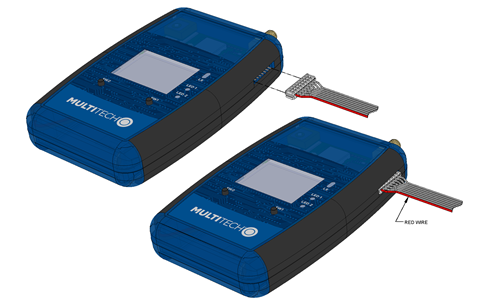
The following three images below and on the left apply for connecting:
- the MTDOT-BOX to the MDK (model: MTMDK-ST-MDOT)
- the MTDOT-EVB to the MDK (model: MTMDK-ST-MDOT)
For UDK2 users (who received a note regarding the
programming cable): Due to supplier error on some devices,
the connection is the opposite way for connecting (see second UDK2
image on the right):
- the MTDOT-BOX to UDK2 (model: MTUDK2-ST-MDOT)
- the MTDOT-EVB to UDK2 (model: MTUDK2-ST-MDOT)
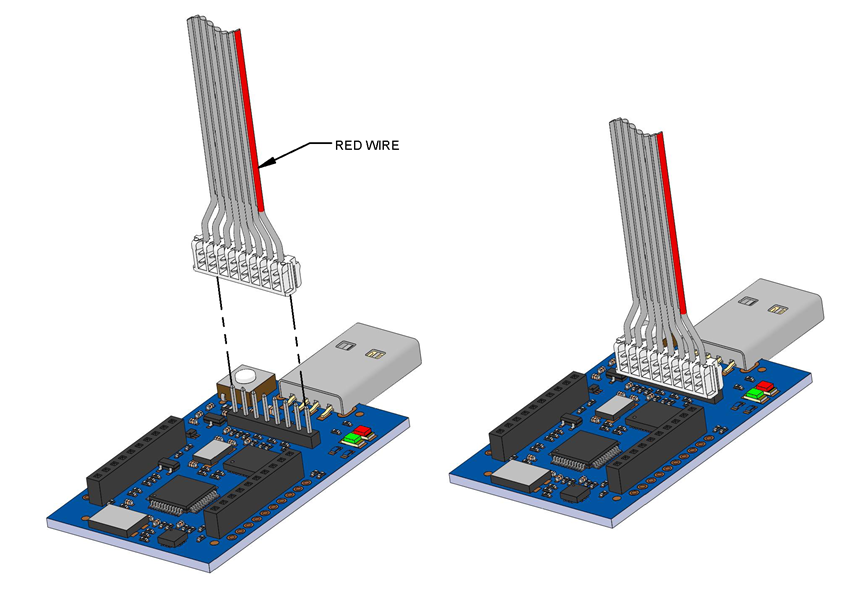
For these users, the red wire on the 8 position programming
cable indicates pin position 8 (on both the device and UDK2).
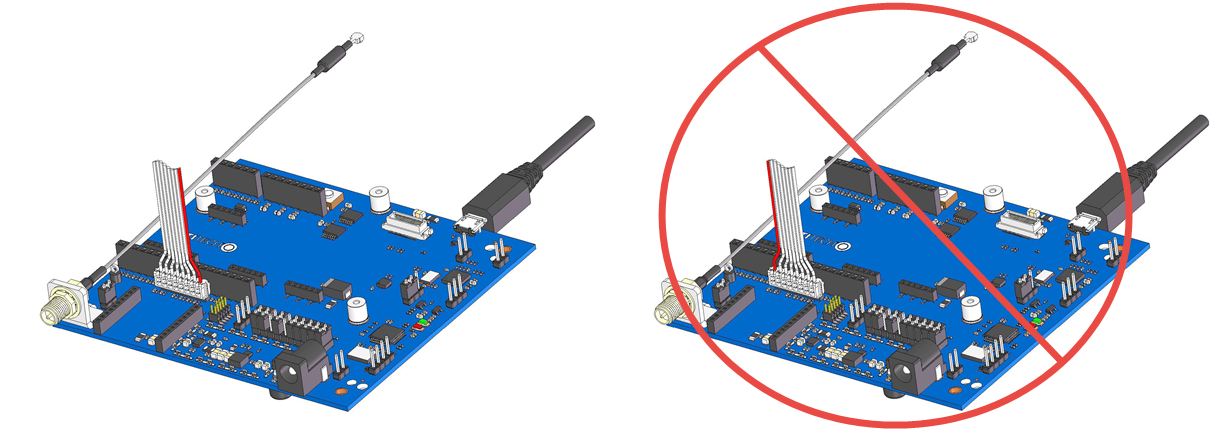
This picture (above) shows the correct UDK2 connection (left) versus the incorrect one (right). Refer to the note for UDK2 users near the top of this page.
If you want to configure or reprogram the device, you must order a Micro Developer Kit (MDK), model: MTMDK-ST-MDOT, (pictured above) which is sold separately. (Alternatively, a UDK2 can also work.) For programming instructions and more details, visit the mbed.org site at: http://developer.mbed.org/getting-started/ and https://developer.mbed.org/platforms/mdotevb
Note: If you do not want to configure the device, configure your gateway to match these device default network parameters:
- name: MultiTech
- phrase: MultiTech
- sub band: 1 (only applies to US/915 MHz Frequency Band)
- region: US915
For Windows users only, you must install the device driver for the configuration port. From the host, use an application such as TeraTerm with a baud rate of 115,200. If the USB driver does not automatically install, do the following:
- Unplug the USB cable.
- Click this link to download and install the appropriate Windows USB driver for EXAR xr21b1411 on the Exar website at: https://www.exar.com/content/document.ashx?id=1596
- Plug the USB cable back into the housing.
- From the host, access the EVB’s USB COM port.
If you have the USB driver already installed, do the following for Configuration Mode:
- As shown above, connect the device to the MDK or UDK2 using the 8-pin flat programming or ribbon cable (with its red stripe facing you). Note: the MDK reset button resets both the MDK and the connected device. But the UDK2reset button only resets the UDK2 itself, not the connected device.
- Connect the MDK or UDK2 to a computer (via its USB connector) after powering up the device. Note: The MTUDK2-ST-CELL requires an external power supply (not powered via USB).
- Using your computer, connect to the new TTY/COM port at 115200 bps.
- Press SW2 to select Configuration from the Main Menu.
- A help screen displays how to connect.
- A second help screen displays a message about connecting to a PC.
- A third help screen displays a message to connect to the new TTY/COM port at 115200 bps.
- Enter the AT command you wish to execute. To see information on the entire set of commands, enter help or ? (without an AT prefix). Below are some commonly-used AT commands.
| AT+NI=1,<name> | Change the Network Name to match your gateway |
| AT+NK=1,<phrase> | Change the Network Passphrase to match your gateway |
| AT+freq=<region> | Change the Region to match your gateway (ex: AT+freq=US915) – available regions include:US915, AS923, AS923-JAPAN, AU915, KR920, EU868, or IN865 |
| AT+FSB=<sub band> | Change the Frequency Sub Band to match your gateway (only applies to US/915 mHz Frequency Band ) |
| AT&W | Save the configuration changes |
6. Hold SW1 or use AT+EXIT to return to the Main Menu.
AT Commands
All commands have a help message that describes the command and how to use it. Enter help or ? (without an AT prefix) to display information for the entire set of commands. The +EXIT command closes Configuration Mode and goes back to the main menu.
Survey Modes Only
The +MINSIZE and +MAXSIZE commands restrict the Survey Sweep to a subset of the available data rates based on the specified minimum and maximum payload sizes.
| AT+MINSIZE | Set/View the minimum payload size (11 – 242, Default: 11) |
| AT+MAXSIZE | Set/View the maximum payload size (11 – 242, Default: 242) |
The +MINPWR and +MAXPWR commands restrict the Survey Sweep to a subset of the available power levels.
| AT+MINPWR | Set/View the minimum transmit power (2 – 20, Default: 2) |
| AT+MAXPWR | Set/View the maximum transmit power (2 – 20, Default: 20) |
The +DATA command enables or disables transmission of data packets during survey operations. This is relevant with the EU/868 MHz frequency band where the duty cycle limitations are more restrictive. Users may not want to use 50% of their potential transmissions to send data to the gateway after a successful survey.
| AT+DATA | Enable transmission of data packet after successful survey (0: off , 1: on, Default: off ) |
| AT+GSDF | Get survey data file contents |
| AT+DSDF | Delete survey data file |
LoRa Demo Mode Only
| AT+TXDR | Set/View the transmit data rate (7 – 10 US, 7 – 12 EU, Default: 7) |
| AT+TXP | Set/View the transmit power (2 – 20, Default: 11) |
Survey and LoRa Demo Modes
| AT | Attention |
| ATI | Show firmware version information |
| AT+DI | View the device ID |
The +FSB command is only applicable for the US/915 mHz frequency band. If the device is operating in public network mode, set the +FSB command to 0 so the device hops all 64 channels. If the device is operating in private network mode, set the +FSB command to 1 – 8 and match the gateway configuration. If the frequency sub band doesn’t match the gateway’s configuration, the gateway does not receive packets from the device.
| AT+FSB | Set/View the frequency sub band (0, 1 – 8, Default: 1) |
| AT+FREQ | View the frequency band (FB 915 or FB 868) |
The +NI and +NK commands each allow the credential to be configured as a string or in hexadecimal. Enter hexadecimal network ID and network key as shown below.
| AT+NI=0,<hex ID> | <hex ID> = 8 bytes |
| AT+NK=0,<hex key> | <hex key> = 16 bytes |
Enter string network name and network passphrase as shown below.
| AT+NI=1,<name string> | <name string> = 8-128 characters (default = MultiTech) |
| AT+NK=1,<passphrase string> | = 8-128 characters (default = MultiTech) |
The +NJM command controls how the device joins the network. In Manual mode, there is no join request sent and the device must be manually configured with a network address (+NA), a network session key (+NSK), and a data session key (+DSK). The device must be provisioned with the network server as well. In OTA mode, the device only needs to be configured with a network name (+NI=1,name) and network passphrase (+NK=1,passphrase). The network session key, data session key, and network address are all automatically configured.
| AT+NJM | Set/View the network join mode | 0: MANUAL | 1: OTA | Default: OTA |
| AT+NSK | Set/View the network session key | hex 16 bytes | ||
| AT+JD | Set join delay in seconds | |||
| AT+DSK | Set/View the data session key | hex 16 bytes | ||
| AT+NA | Set/View the network address | hex 4 bytes | ||
| AT+PN | Set/View public network mode | 0: Private MTS | 1: Public | 2:Private LoRaWAN |
| AT+EXIT | Exit back to the main menu | |||
| AT&V | View current configuration | |||
| AT&W | Save current configuration | |||
| AT&F | Revert to factory default configuration |
MDK/UDK2 Troubleshooting
“There is not enough space on MULTITECH”
- Unplug the MDK/UDK2 from USB and plug it back in.
- If using UDK2, disconnect the USB cable and power supply. First, reconnect the power supply, and then reconnect the USB cable.
Windows prompts me to install drivers
- Cancel any driver installation prompts. The MDK/UDK2 mounts as the MULTITECH drive without drivers.
- Drivers are only needed for the virtual USB COM port. Installation instructions and files are available on the ARM mbed site.